
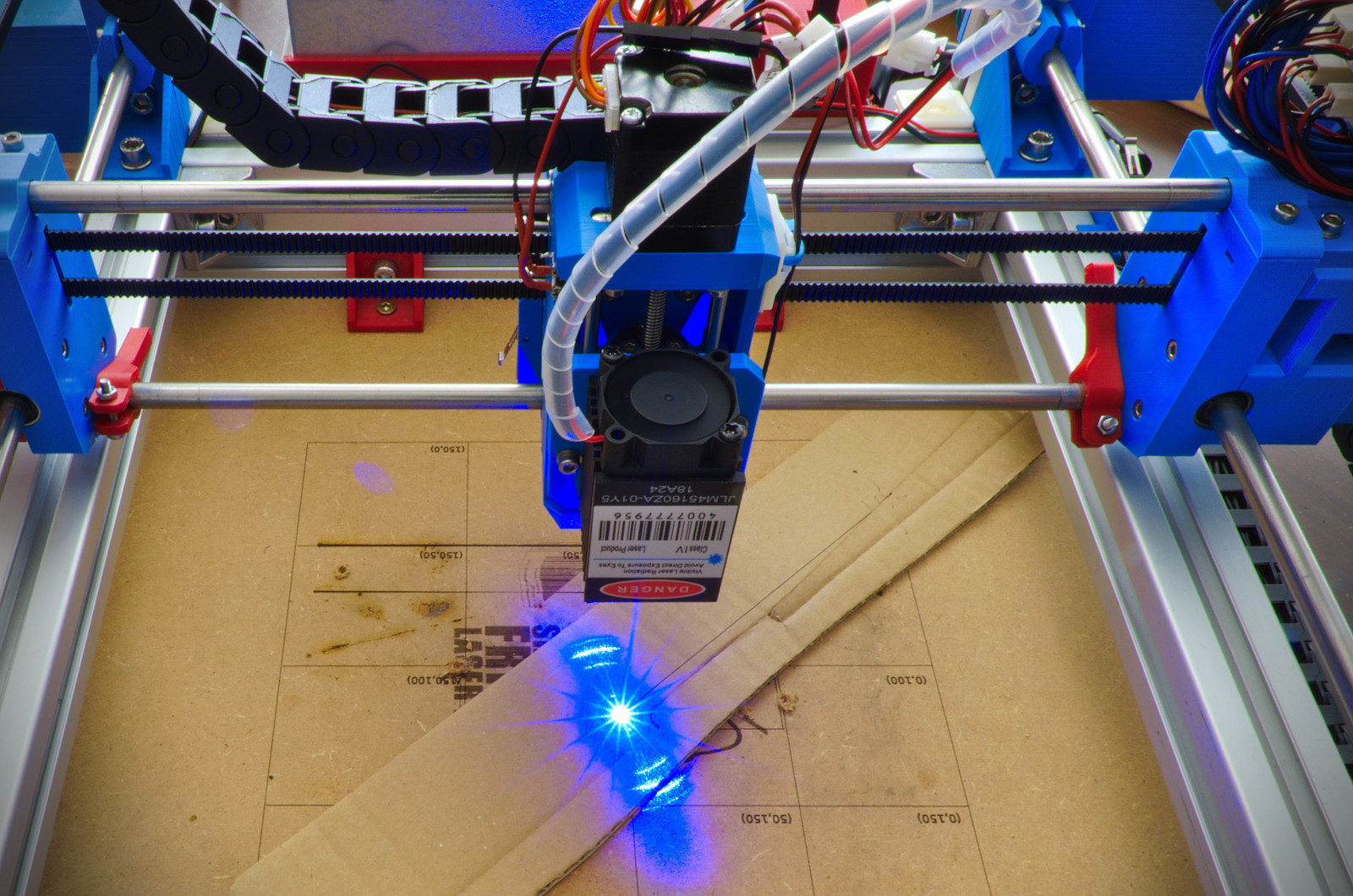
Update time! The CoreXY Laser Engraver has been updated with a motorized Z axis and numerous other enhancements… like more laser power. Har Har Har!
When Jogi posted his make on Thingiverse he already added many improvements over my initial design, like cable chains, larger build area and overall cleanliness (I’ll address this one in Mk3 😉 ). We started discussing about a Z axis and it got me hooked up right away. Here’s the result!
Implemented changes
Check out the original version for a general overview of the machine and its purpose. With this new revision I mainly addressed the following issues:
- A motorized Z axis was added with effective 50 mm travel range
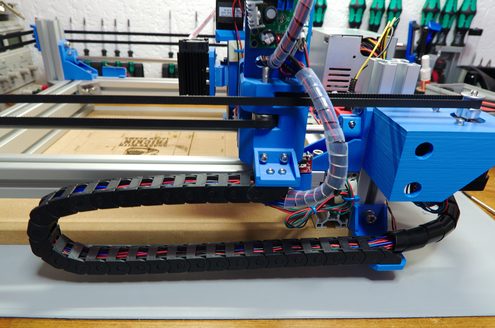
- Chain belts have been added
- Adjustable X rod mount to fine tune the rod spacing in case of mechanical issues
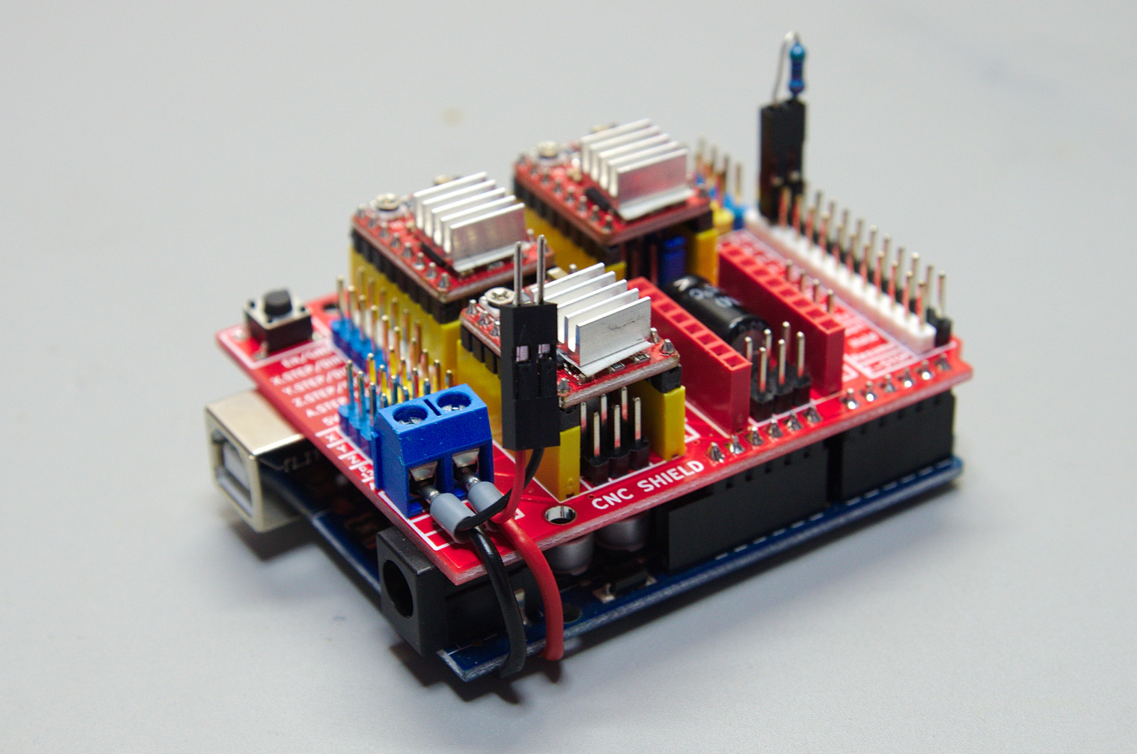
- Switched the controller to Arduino Uno + CNC Shield to implement hardware limits (not possible with RAMPS board)
- Added a pull-down resistor to keep the laser off during GRBL boot
- Three control buttons for feed hold, start/resume and reset/abort functionality
- Fan-cooling added to stepper drivers
More details to the individual changes are listed below. But first, some images. 🙂
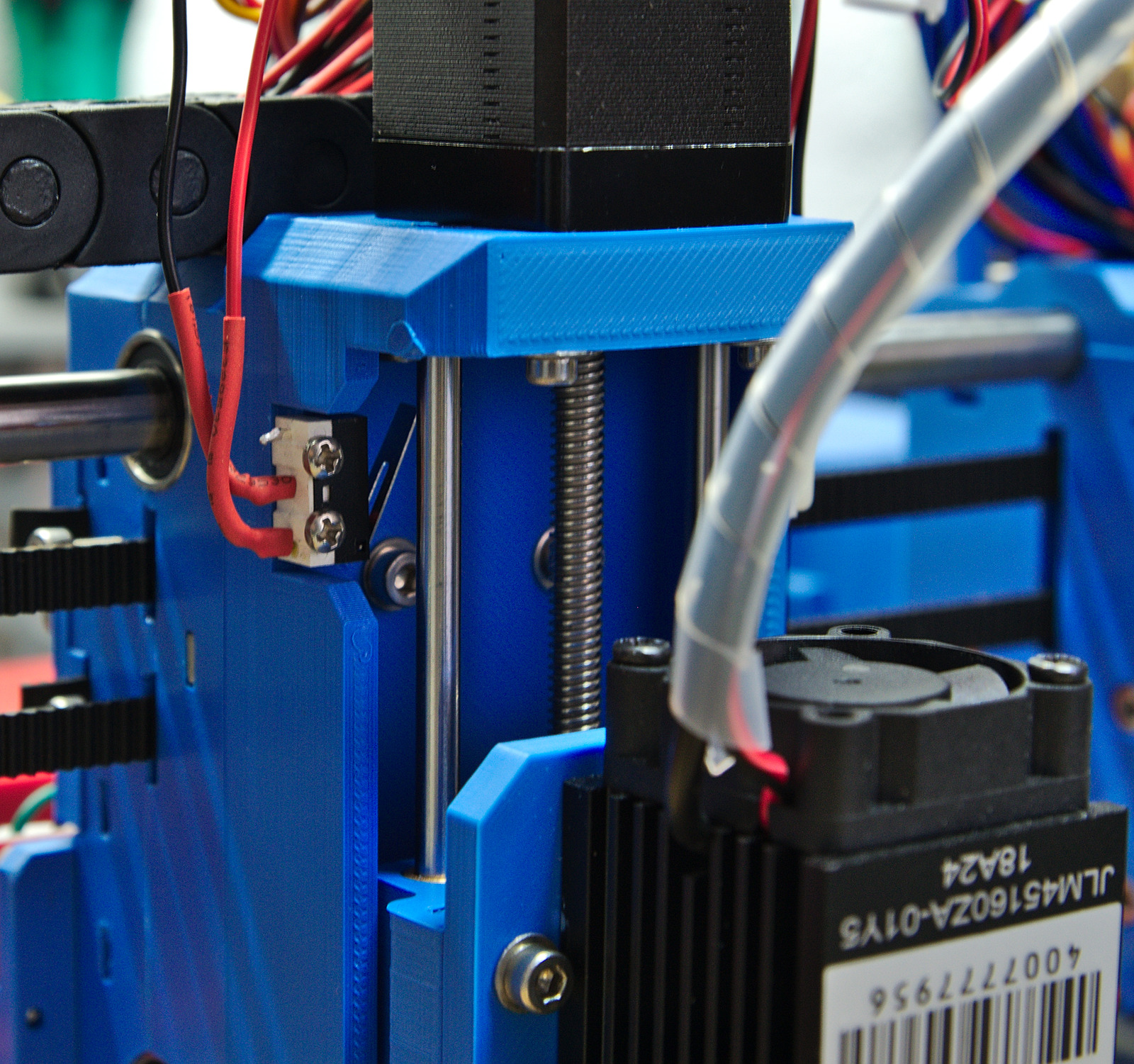
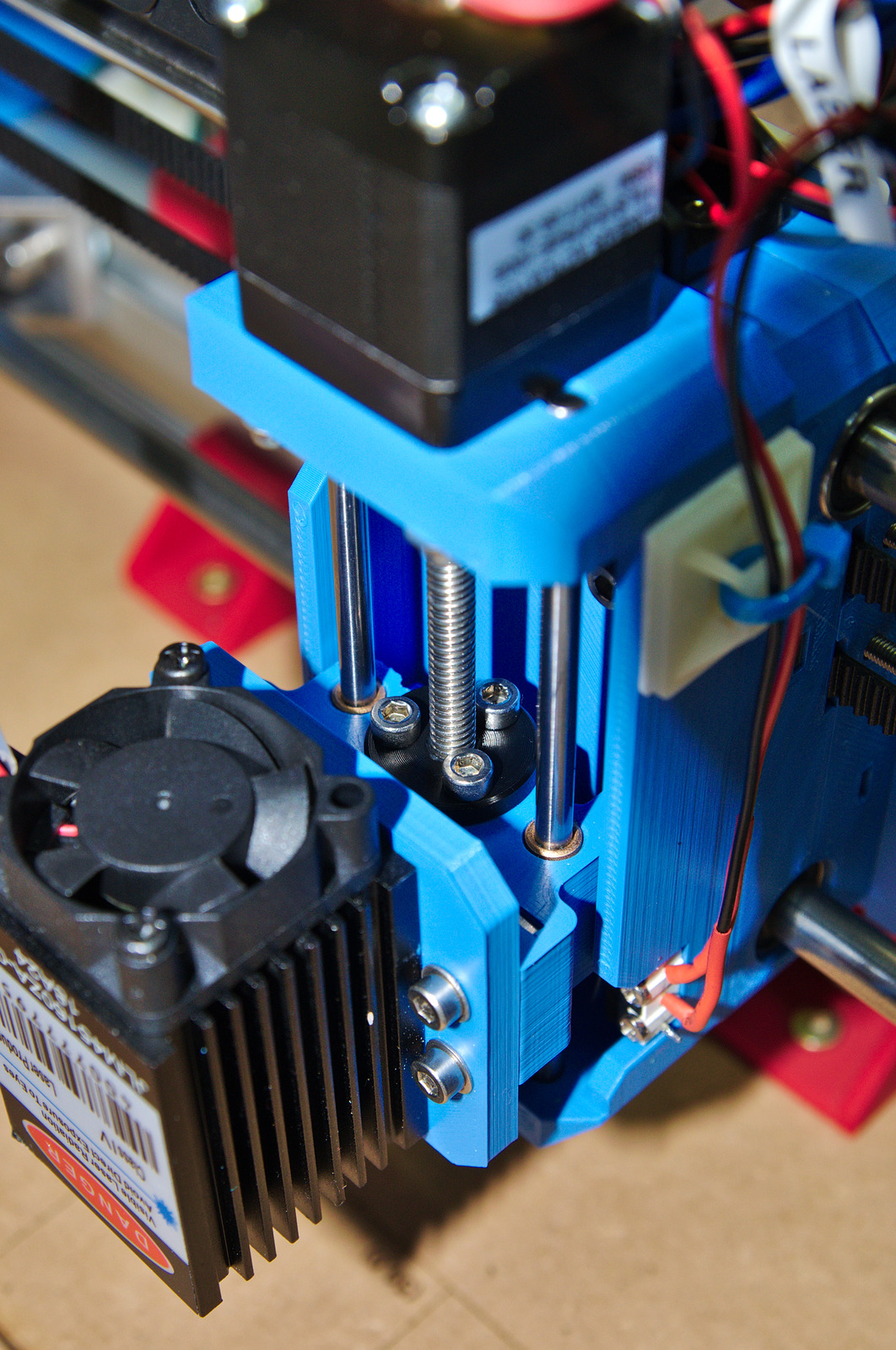

Z-axis
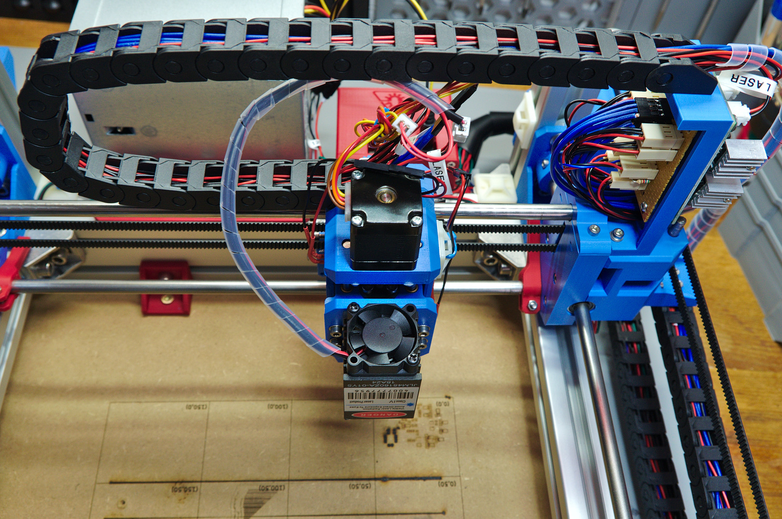
A Nema11 stepper with an integrated 5 mm diameter / 2 mm pitch trapezoidal screw drives the z axis. The motion stage is guided by 4 mm rods and brass bushings. The additional parts reduce the Y-axis travel range about 30 mm while the usable X-range is unchanged. In the end the machine has a 210x190x50 mm work dimensions with the rod dimensions listed below, while X and Y range can be easily increased.
Chain belts
All cables are routed through 10×10 mm chain belts. On top of the Y carriage is a mounting plate for the laser driver, as well as a connector board for easier disassembly. Note to self: next time don’t use closed chain belts. And buy multi-wire cables…
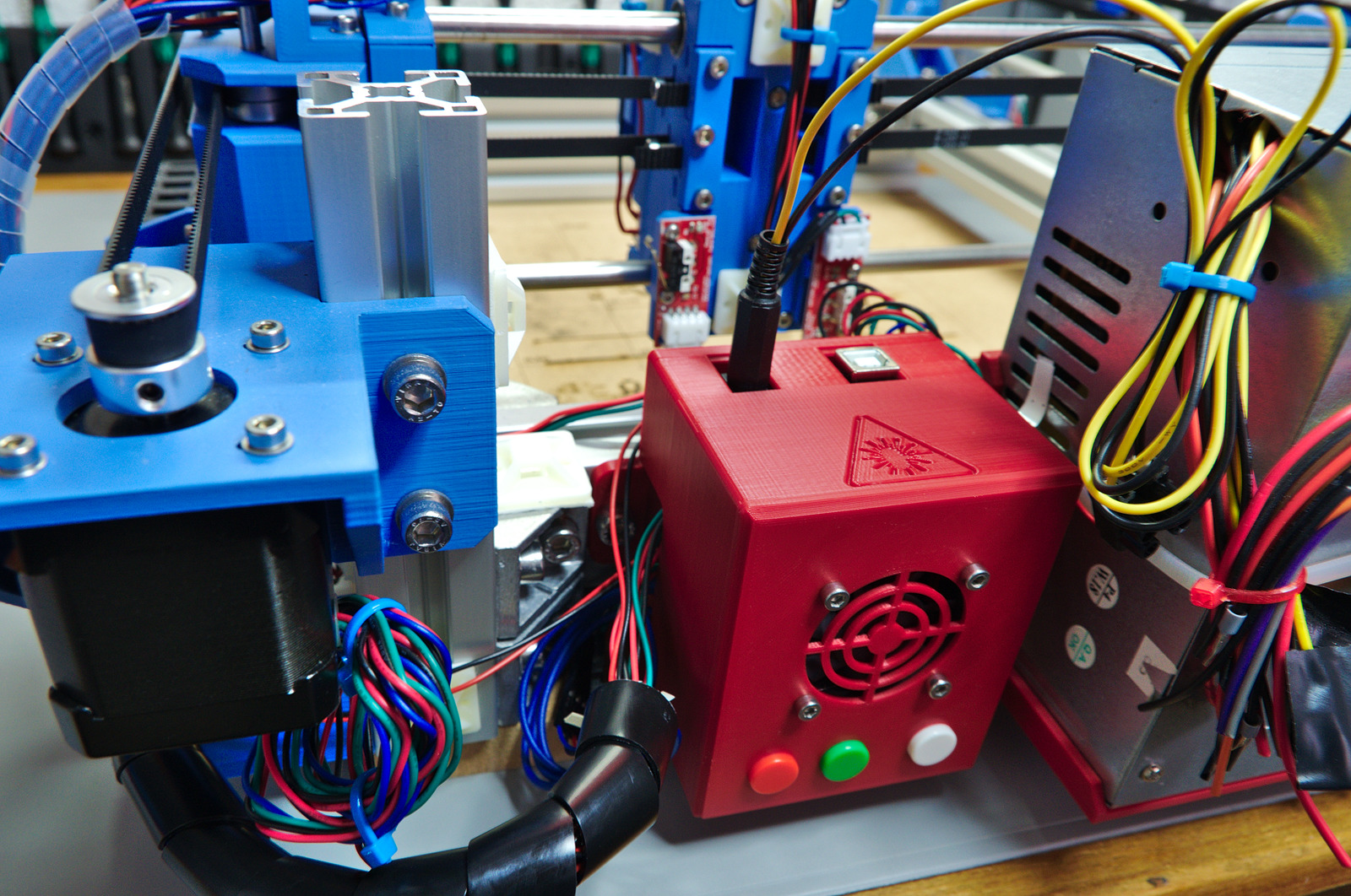
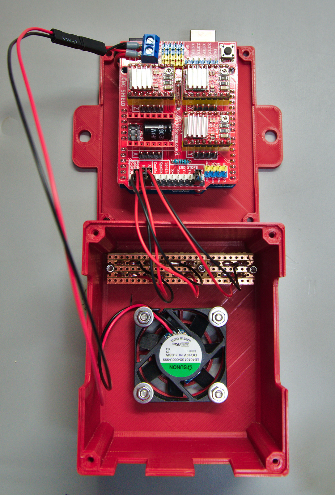
Electronics & Firmware
The electronics has been replaced with an Arduino Uno + CNC Shield. For one thing it’s smaller and, more importantly, allows to use the endstops as hardware limits. Not more accidental crashing into the frame.
I also added 3 buttons to the control box which are wired to the “feed hold”, “start/resume” and “abort/reset” pins. Hold and resume is a pretty neat feature of GRBL…
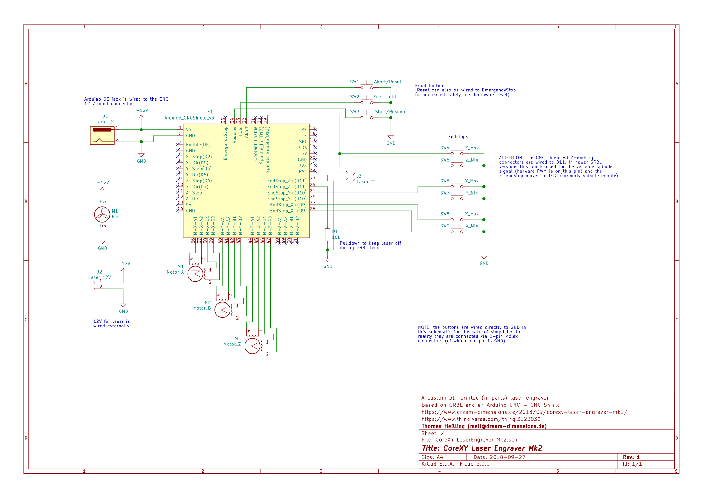
The spindle enable pin is now equipped with a pull-down resistor to prevent the laser from turning on during GRBL boot. Its value doesn’t really matter, just use 1k or higher.
IMPORTANT NOTE: The CNC shield was designed for an older GRBL version. Newer versions have a different pin layout when using a variable spindle, i.e. PWM to control the speed/laser power like we do. The spindle enable and Z axis limit pins must be switched! Refer to the schematic picture above.
There’s a pre-configured GRBL version available on GitHub.
X carriage
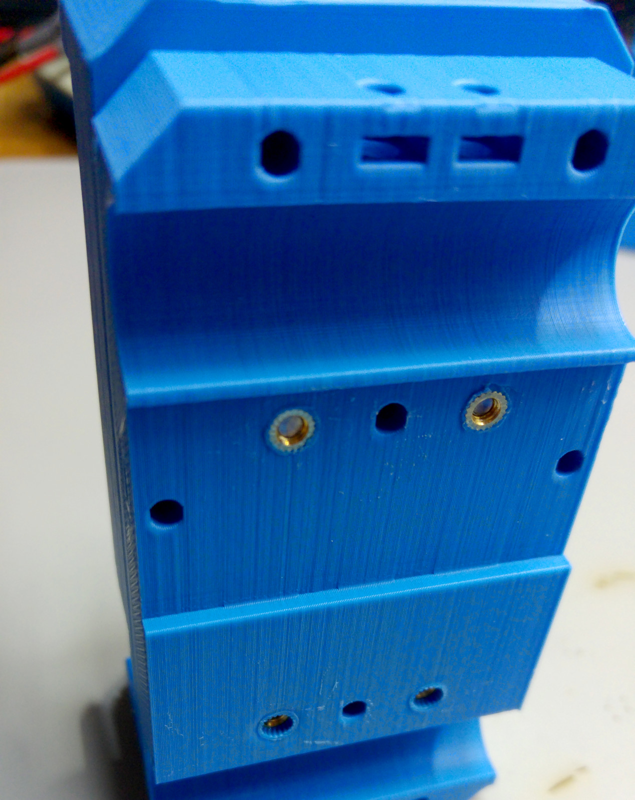
On the original build the laser driver was fastened with regular M3 hex nuts you placed into the X carriage. I found this quite frustrating at time since they move around and potentially twist. In the Mk2 version they are replaced by M3 thread inserts that you melt into the plastic.
The X rod mounts are split into two. On my first machine there have been some motion issues due to small misalignment of the X axis. With the two-part-design you can add small shims to adjust the X-rod spacing for smoother movement. Of course, now that I have the ability to fine-tune, the assembly is moving smoothly without any modification…
Parts List
This is a (hopefully) complete list of all parts required for this build.
Electronics
- 1x Arduino Uno
- 1x Arduino CNC Shield
- 3x Stepper driver (A4498, DRV8825, SilentStepStick)
- 4x Endstops (Makerbot)
- 2x Microswitches (13 mm length)
- 3x 12 mm round push buttons
- 1x stripboard, approx. 66×15 mm
- 1x Laser with TTL driver (+fan if not integrated)
- 1x 12V Power supply (e.g. old ATX)
- 1x Fan 12V (for the electronics case)
- 2x Nema 17 stepper motor
- 1x Nema 11 stepper with 100 mm integrated trapezoidal screw (see link above)
Mechanics
- 2x 8 mm Rods, 370 mm (Y axis)
- 2x 8 mm Rods, 330 mm (X axis)
- 2x 4 mm Rods, 100 mm (Z axis)
- 8x LM8UU linear bearing
- 4x brass bushing, 4x6x8 mm
- 16x Ball bearing 625 ZZ
- 6x 5mm steel rod, 40 mm (for fastening the ball bearings)
- 2x GT2 Pulley, 16 teeth
- ca. 4m GT2 belt
- 2x Aluminum profile, 30×30 B (8 mm slot), 325 mm
- 4x Aluminum profile, 30×30 B (8 mm slot), 100 mm
- 2x Aluminum profile, 30×60 B (8 mm slot), 360 mm
- 12x Corner mounting brackets 30×30
- 10×10 mm chain belts
Screws
- M6 T-slot nuts
- M6 screws
- M3x16 head cap screw
- M3x20 head cap screw
- M3x25 head cap screw
- M3 square nuts
- M3 hex nuts
- 4x M3 thread inserts
- M2x10 mm screws (for the Z end stop switches)
- Thermoplastic screws, 2.5 mm & 3 mm (endstops, Arduino mounting, etc.)
Instructions
Right now I am working on more detailed instructions on how to assemble this engraver, but this might take a while. Until then I hope these instructions give a rough roadmap. If you have any questions feel free to contact me.
3D printed parts
Before you begin here’s a list of how many times you’ll have to print each STL file. All files are available for download at the bottom.
- Print these 4 times:
- Y_axis_mount.STL
- belt_pusher.STL
- base_mount_angle.STL (optional)
- Print these 2 times:
- belt_diverter.STL
- belt_clamp.STL
- X_endstop_trigger_clamp.STL
- Ycarriage-front-_Part_A.STL
- Ycarriage-front-_Part_B.STL
- Y_endstop_mount.STL
- Print these 1 time:
- Arduino_Uno_CNCCase-_Part_A.STL
- Arduino_Uno_CNCCase-_Part_B.STL
- ATX_power_supply_mount.STL
- cable_chain_mount_X.STL
- cable_chain_mountY-_A.STL
- cable_chain_mountY-_B.STL
- laser_mounting_plate.STL
- Nema17_mount.STL
- Nema17mount-_left.STL
- Xcarriage-_back.STL
- Xcarriage-_front.STL
- X_endstop_mount.STL
- X_endstopmount-_left.STL
- Ycarriage-_back.STL
- Ycarriage-_back_left.STL
- Z_axis_cage.STL
- Z_carriage.STL
Assembly order
The rough order of assembly is as follows, the details are left as an excercise to the reader (i.e. I’m working on a more detailed version… we’ll see… 😉 )
- Assemble the aluminum frame
- Add the ball bearings to the parts that need them
- Put M3 nuts in place where needed
- Put the two Y rods with Y axis mounts into the frame (don’t forget the LM8UUs)
- Assemble the X rods with the X_carriage_front parts (the bottom screw is tricky to tighten once it’s attached to the Y axis)
- Put the X rods inbetween the Y rods. It should hold by itself when placed onto the LM8UU bearings. Then add the Y carriage back parts
- Attach the X carriage front and back (mount the end stops and belt clamps first)
- Insert the Z rods and Z motor into the Z cage. Don’t forget the Z carriage, it can’t be added later on
- Add the Z endstops and mount the assembled cage to the X carriage
- Mount the X/Y motors with GT2 pulleys
- Run the belt along its path and fasten both on one side of the X carriage
- Insert the belts on the other side now. Make sure the tensioners are loose. Fasten them after the belt has been properly clamped
- Mount the Y endstops and X endstop trigger clamps
- Mount the cable chains and route all the wires
- Connect the wires to the Arduino CNC shield and/or power supply
- Install GRBL, test, fix errors, have fun engraving! 😀
First-run checklist
After the assembly is done the firmware has to be flashed to the Arduino and properly configured. There are a few steps that you should always perform to save you lot’s of trouble later on.
- Microstepping
The GRBL version I posted on GitHub assumes a specific hardware / electronics configuration. X and Y are assumed to use 32x microstepping, Z 4x microstepping.
Also the belt is assumed to be GT2 (2 mm spacing), the pulleys to have 16 teeth and the Z-screw to have a 2 mm pitch. If your configuration is different you have to tune your GRBL differently. - Stepper motor direction
The direction each stepper turns for given signals from the controller is hard to tell without trying it. You can change a motor’s rotation direction by flipping its 4-pin connection.
At the beginning you should check if every motor moves as expected. Manually place each carriage in the center of its range and send GRBL jogging commands, e.g. from UGS Platform software.
The machine is configured to have it’s origin in the lower left part when looking at it from the electronics end. Ensure that a +X movement command moves the carriage to the right, a +Y movement away from you and a +Z movement downwards. - Spatial calibration
Make sure your steps/mm is correct for all axes by measuring them. - Hardware limits
Make sure all hardware switches trigger correctly and put GRBL into Alarm mode.