
Many electronics projects need some kind of user input. For those where you need scrolling functionality, in a menu for example, or enter numerical values like a timeout, rotary encoders are very convenient. They are cheap, easy to use and require minimal to none additional components. However, interfacing them requires little more work on the software side than with regular buttons. In this tutorial I present everything needed to use a rotary encoder with a microcontroller. While I used an ATmega uC it should be easily portable to other platforms
The Hardware
Before going into too much detail let me point out this post focuses on simple rotary encoders designed for manual user input. Their electrical interface consists of three pins (or five, if there’s a push button integrated) of which two are signal pins and one common connection. The two signal pins will output a Gray code (details follow later) depending on the rotation direction. Mechanical feedback is provided by a certain number of indexing positions per revolution, e.g. my encoders have 24 indexes per revolution. If you move the shaft from one position to the next a signal is generated.
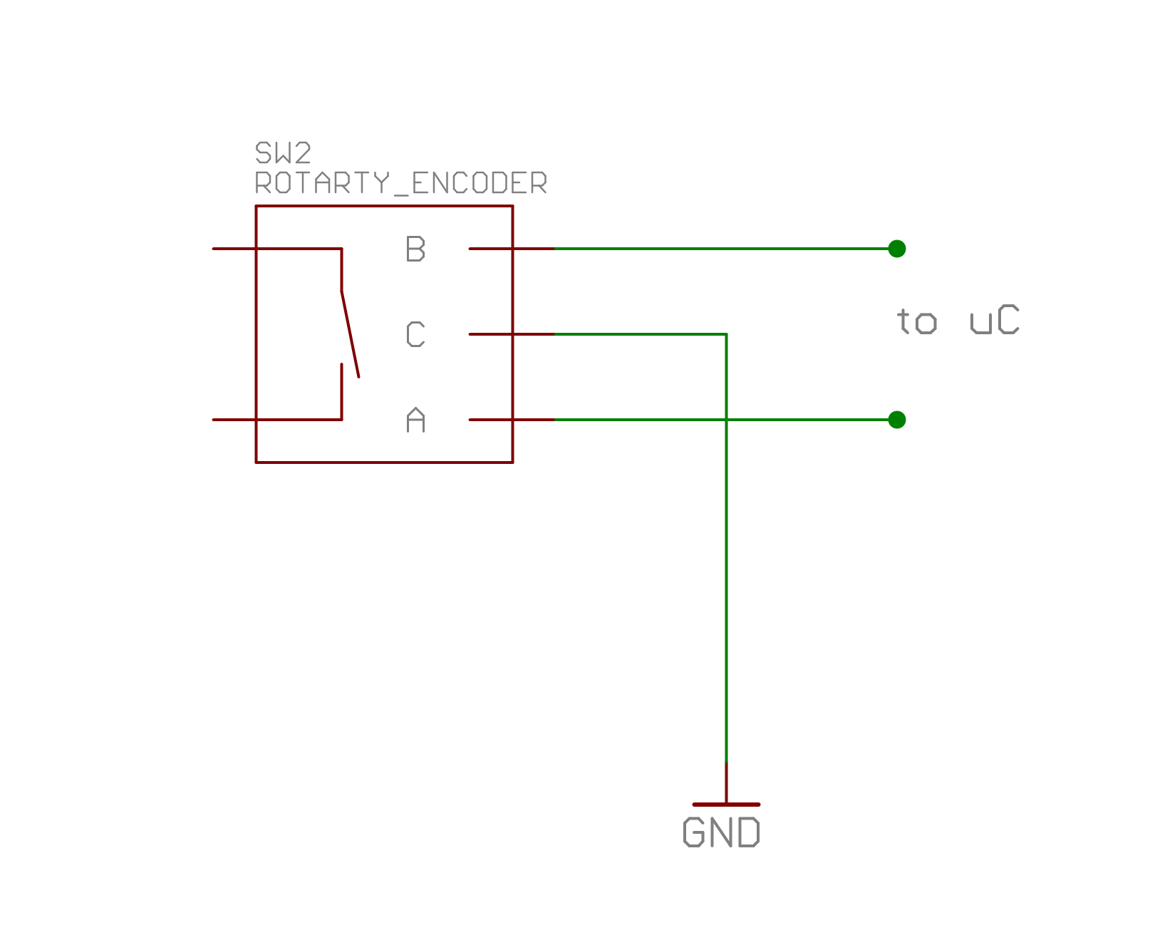
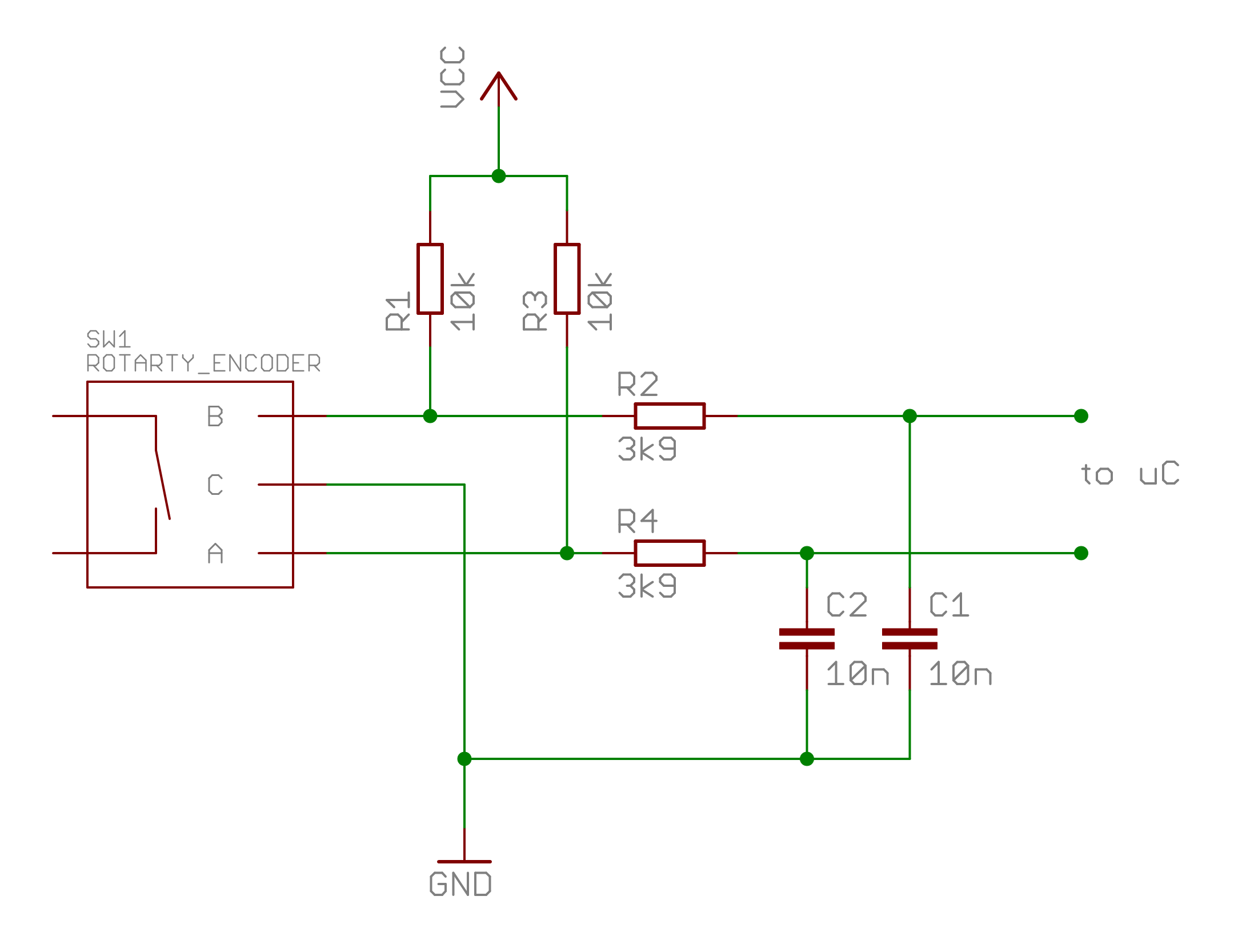
At first the encoder needs to be connected to your microcontroller. In the simplest case you can use the microcontroller’s internal pull-up resistors with the advantage that no additional components are required (refer to Fig. 1). The common line is always connected to GND. The switches within the encoder do bounce on every step and there are several ways to deal with this: additional circuitry, design a robust algorithm or simply ignore it. Although ignoring it worked pretty fine in my test setup I added a debounce feature into the algorithm. If you want the best protection against bouncing you should use the circuit in Fig. 2 with additional low passes on each signal line (note that the internal pull-ups cannot be used with this). I did not test the second circuit, you might need to adapt the values to your needs. The resistance for the pull ups is determined by the maximum current the encoder can handle, check the datasheet.
How it works
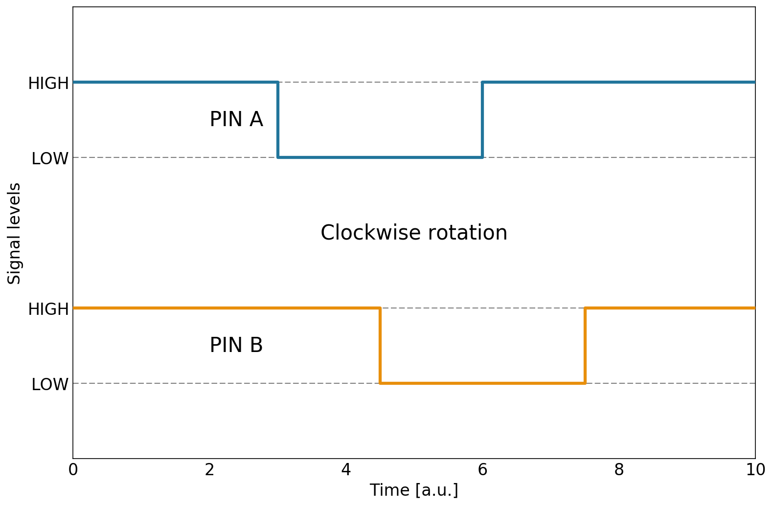
Now that the basic circuit is done and connected to the controller it’s time to talk about the working principle of rotary encoders. Both signal lines are, from a user’s perspective, nothing more than two switches. Whenever the shaft is rotated both of them are shortly connected to ground, causing their logical level to go from VCC to GND. Depending on the direction of rotation the transition of pin A precedes that on pin B, or vice versa. If no rotation occurs both pins are at high level due to the pull up resistors. This principle is illustrated in the Figures below for a single step.
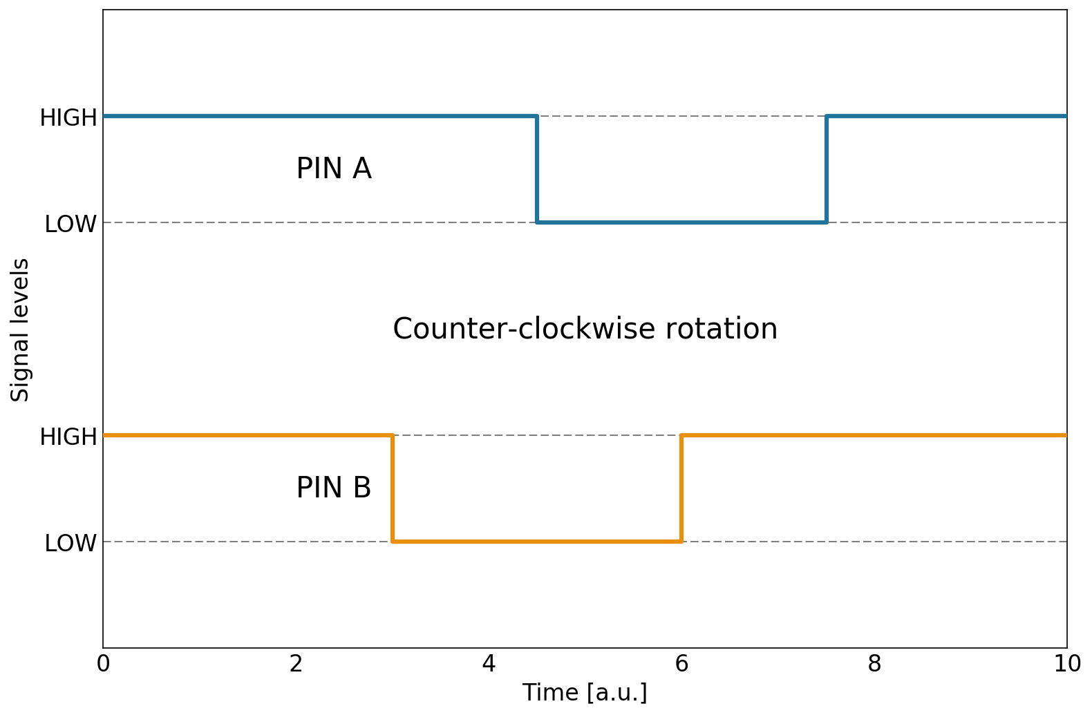
From these pictures you can easily deduce an algorithm that will detect which direction the knob was turned. When both signals are HIGH nothing happened, just keep waiting. If either pin A or B are LOW but not the other one we wait for the second one to change. Depending on which one turned LOW first the rotation direction is already known at this point. Nevertheless we have to wait until the other pin goes LOW, too, so that the cycle is actually complete.
Note that this explanation is for indexed encoders, where for each rotational step the depicted cycle occurs. Rotary encoders without indexing positions work the same way but they can also remain in the LOW state when at rest. This basically means you need to look out for a change in the signal level instead of waiting for LOW to capture all events. Most types for user inputs are indexed though, so I will leave this modification as an exercise to the reader. 😉
The algorithm
From the description above it gets clear that all we have to do is query the encoder’s pins. There are basically two ways to do this: use the controller’s interrupts or regularly poll the current state. In many applications interrupts are superior to polling because they use far less CPU resources. However, if mechanical connections are involved, their ubiquitous bouncing can lead to many ghost trigger events unless you electrically debounce them. In this case I will use a polling routine that periodically queries the pin states. In fact, many applications use a display or some other stuff that requires a periodic timer anyway, so no real harm done.
The polling frequency
If we are polling we have to make sure the frequency with which we are polling is high enough to not miss any events. The best way would be to connect the encoder to an oscilloscope and see how fast you can turn the knob. Unfortunately I don’t own an oscilloscope but there are other ways. At first I connected one pin to my multimeter and measured the frequency. The highest frequency were somewhere in between 100 Hz and 200 Hz. Usually you would turn the knob way slower. The datasheet mentions a guaranteed debounce time of 5 ms so querying every 1 ms should be more than enough. In a practical setup I achieved reliable results with a frequency of 500 Hz. Just try it out.
The basic layout
The basic flow of operation is quite simple. State variables are used to keep track of where in the Gray code we currently are, i.e. if we are waiting for any pin to go LOW, if one pin is already LOW and the other still HIGH etc. These variables are updated every time the timer creates an interrupt. Within the main loop you can then trigger further actions depending on the rotation detected. I added a 16bit position variable to the state struct which is incremented on CW and decreased on CCW rotations.
Software debounce
Since I didn’t use the low-pass circuit described above I added a software debounce. Whenever a pin change is detected we wait a configurable number of timer interrupts and then check the pin again. If it is still LOW we are good, if not it was just some bounce, noise, whatever and we return to the initial waiting state. However it seems the encoder works pretty reliably even without this feature. Also, I only utilize this for the first pin change, not the second one.
The rotary encoder state
If you look a the sample gray code above (Fig. 3 and 4) the following states can be deduced:
- WAIT: both pins are high
- WAIT_A_STAB: Pin A has changed, wait for it to stabilize (debounce)
- WAIT_B: Pin A stabilized, wait for B to change
- WAIT_B_STAB: Pin B changed first, wait for it to stabilize (debounce)
- WAIT_A: Pin B stabilized, wait for A to change
- ROT_CCW: Counter-clockwise rotation occured (Pin A before B)
- ROT_CW: Clockwise rotation occured (Pin B before A)
An algorithm can successively move from the WAIT state to the lower ones until it eventually reaches one of the rotation states. Then, a position counter can be in- or decreased accordingly. If you want to look at a working example you can download it at the bottom or get it from GitHub at:
https://github.com/RealNagus/rotaryencoder.
It’s intended to be used with the simplest hardware circuit shown above. The position is stored and reported via UART so you can easily watch it change on your PC with a FT232-USB converter. If you have any remarks/questions feel free to contact me.